```
!\[\]\(([^\)]*)\)
 ```
> Why are the drawings bad?
I draw them with a mouse
### Etc
#### FIRST-PASS CHECKS
- Double check all are in the correct phase! Multiplications and divisions by $\sqrt{3}$ or $3$ where necessary must be checked! Try annotating everything that does not have an associated phase.
- Check conjugate in current. $\bar{S}=\bar{V}\bar{I}^*$
- Check transformer parameters are referred to the proper side
#### Y-$\Delta$ transformation (Balanced case)
$Z_\Delta=3Z_Y$
### Types of power factors (From `ENSC2003`)
Where $\bar{S}=|\bar{S}|\angle\varphi$:
$$ \varphi = \arctan\left(\frac{Q}{P}\right) = \theta_v-\theta_i$$
| | Lagging | Leading | Unity |
| ----------- | -------------- | ------------- | ------------ |
| Voltage | Current behind | Current ahead | In phase |
| Load type | Inductive | Capacitive | Resistive |
| $Q$ | $Q>0$ | $Q<0$ | $Q=0$ |
| $\varphi$ | $\varphi>0°$ | $\varphi<0°$ | $\varphi=0°$ |
| PF [Load] | $[0,1)$ | $[0,1)$ | $1$ |
| PF [Source] | $[0,-1)$ | $[0,-1)$ | $-1$ |
## Power types in induction motor
| Type | Description | Equivalent terms |
| ------------------ | ---------------------------------------------------------------------------------------------------------------- | -------------------------------------------------------------------------------------------------------------- |
| Input power | Power into machine. $V_T=V_{3\phi}$, $I_L=I_{3\phi}$ | $P_\text{in}$, $\sqrt{3}V_TI_L\cos(\theta)$ |
| Output power | Mechanical output power of the machine, excludes losses | $P_\text{out}$, $P_\text{load}$ |
| Converted power | Total electrical power converted to mechanical power, includes useful power and mechanical losses inside machine | $P_\text{conv}$, $P_\text{converted}$, $P_\text{mech}$, $P_\text{developed}$, $\tau_\text{mech}\times\omega_m$ |
| Airgap power | Power transmitted over airgap. | $P_\text{AG}$, $\tau_\text{mech}\times\omega_s$ |
| Mechanical loss | Power lost to friction and windage | $P_\text{mechanical loss}$, $P_\text{F\\\&W}$, $P_\text{friction and windage}$ |
| Core loss | Power lost in machine magnetic material due to hysteresis loss and eddy currents | $P_\text{core}$ |
| Rotor copper loss | Due to resistance of rotor windings | $P_r$, $P_\text{RCL}$ |
| Stator copper loss | Due to resistance of stator windings | $P_s$, $P_\text{SCL}$ |
| Miscellaneous loss | Add 1% to losses to account for other unmeasured losses | $P_\text{misc}$, $P_\text{stray}$ |
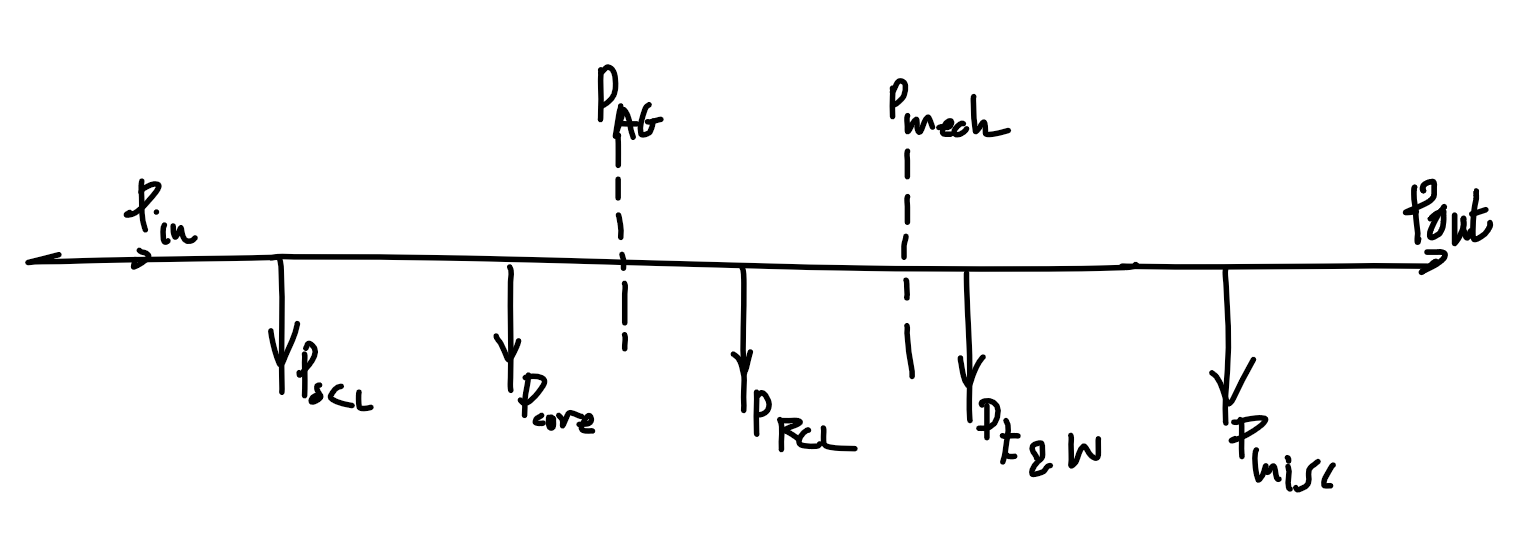 $$
\begin{align}
P_\text{in}&=P_\text{SCL}+P_\text{RCL}+P_\text{core}+P_\text{F\\\&W}+P_\text{misc}+P_\text{out}\\
P_\text{AG}&=P_\text{RCL}+P_\text{F\\\&W}+P_\text{misc}+P_\text{out}\\
P_\text{mech}&=P_\text{F\\\&W}+P_\text{misc}+P_\text{out}
\end{align}
$$
Note - assume loss is 0 if not mentioned!
| Type | Description | Symbols |
| ------------------------- | ------------------------------------------- | --------------------------------------- |
| Load torque, Shaft torque | Torque experienced by load after all losses | $\tau_\text{load}$, $\tau_\text{shaft}$ |
## $3\phi$ induction motor
### Etc.
- Slip speed $N_\text{slip}=N_{s\text{ (sync)}}-N_r=sN_{s\text{ (sync)}}$
- "1/4 of rated load" != "1/4 times full load"
- Means 1/4 of full load slip as it is in the linear region. Accounts for the minimum load.
- Rated power stated in machine specification refers to the output power $P_\text{out}$, and excludes all losses.
- Speed regulation using machine speed: $$\text{SR}=\frac{N_{r,\text{NL}}-N_{r,\text{FL}}}{N_{r,\text{FL}}}$$
### Diagram
$$
\begin{align}
P_\text{in}&=P_\text{SCL}+P_\text{RCL}+P_\text{core}+P_\text{F\\\&W}+P_\text{misc}+P_\text{out}\\
P_\text{AG}&=P_\text{RCL}+P_\text{F\\\&W}+P_\text{misc}+P_\text{out}\\
P_\text{mech}&=P_\text{F\\\&W}+P_\text{misc}+P_\text{out}
\end{align}
$$
Note - assume loss is 0 if not mentioned!
| Type | Description | Symbols |
| ------------------------- | ------------------------------------------- | --------------------------------------- |
| Load torque, Shaft torque | Torque experienced by load after all losses | $\tau_\text{load}$, $\tau_\text{shaft}$ |
## $3\phi$ induction motor
### Etc.
- Slip speed $N_\text{slip}=N_{s\text{ (sync)}}-N_r=sN_{s\text{ (sync)}}$
- "1/4 of rated load" != "1/4 times full load"
- Means 1/4 of full load slip as it is in the linear region. Accounts for the minimum load.
- Rated power stated in machine specification refers to the output power $P_\text{out}$, and excludes all losses.
- Speed regulation using machine speed: $$\text{SR}=\frac{N_{r,\text{NL}}-N_{r,\text{FL}}}{N_{r,\text{FL}}}$$
### Diagram
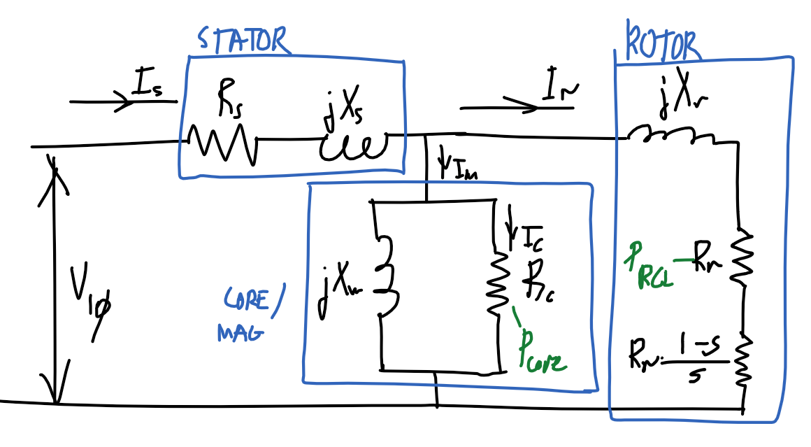 ### Equivalent model
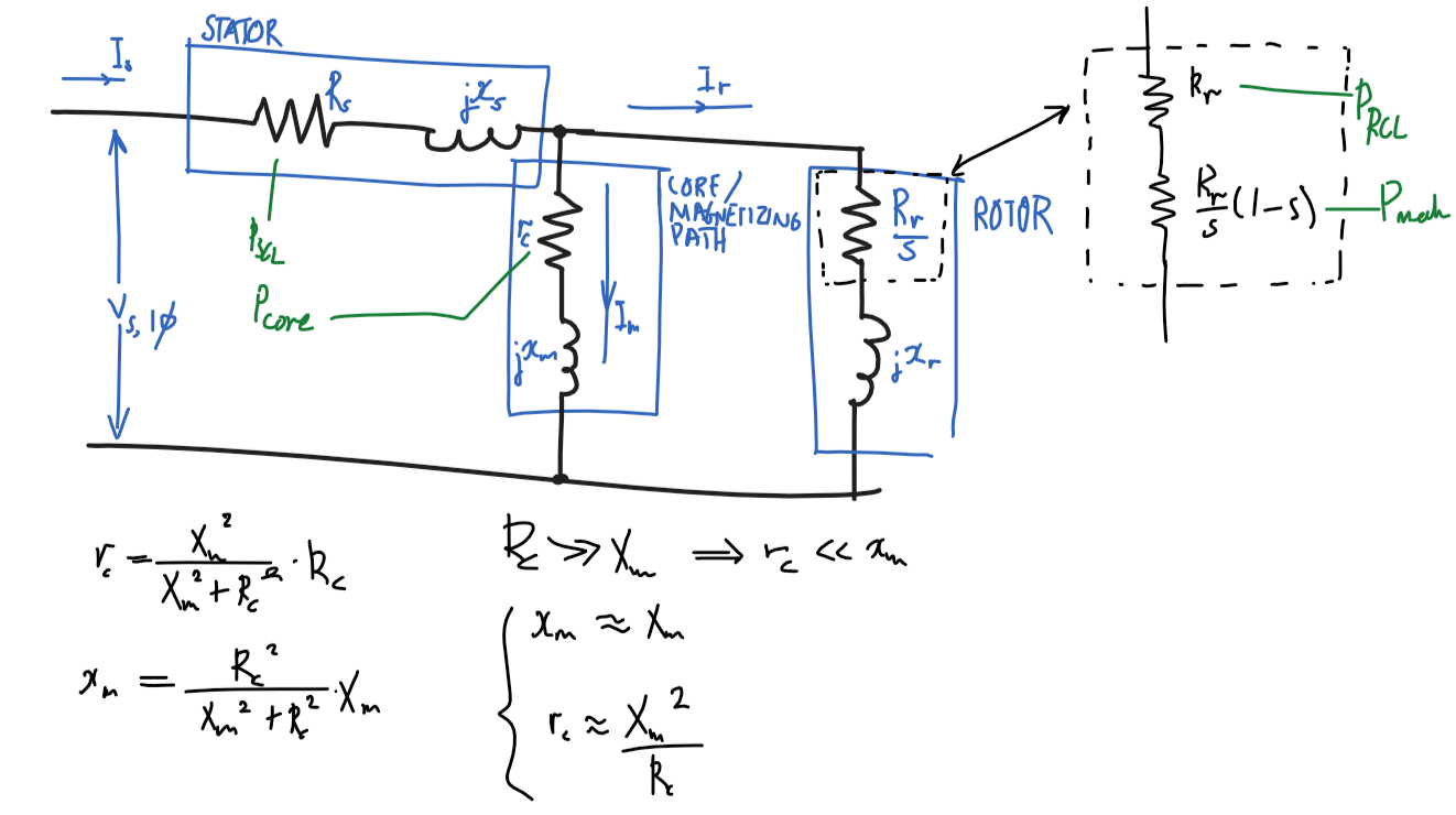
#### Assumptions
- $x_m\approx X_m$
- $R_c\ggg X_m\Rightarrow r_c\lll x_m$
- $x_m=\frac{{R_c}^2}{{R_c}^2+{X_m}^2}X_m\approx\frac{\cancel{{R_c}^2}}{\cancel{{R_c}^2}}X_m=X_m$
- $r_c\approx {X_m}^2/R_c$
- $R_c\ggg X_m\Rightarrow r_c\lll x_m$
- $r_c=\frac{{X_m}^2}{{R_c}^2+{X_m}^2}R_c\approx\frac{{X_m}^2}{{R_c}^2}R_c=\frac{{X_m}^2}{R_c}$
### Diagram
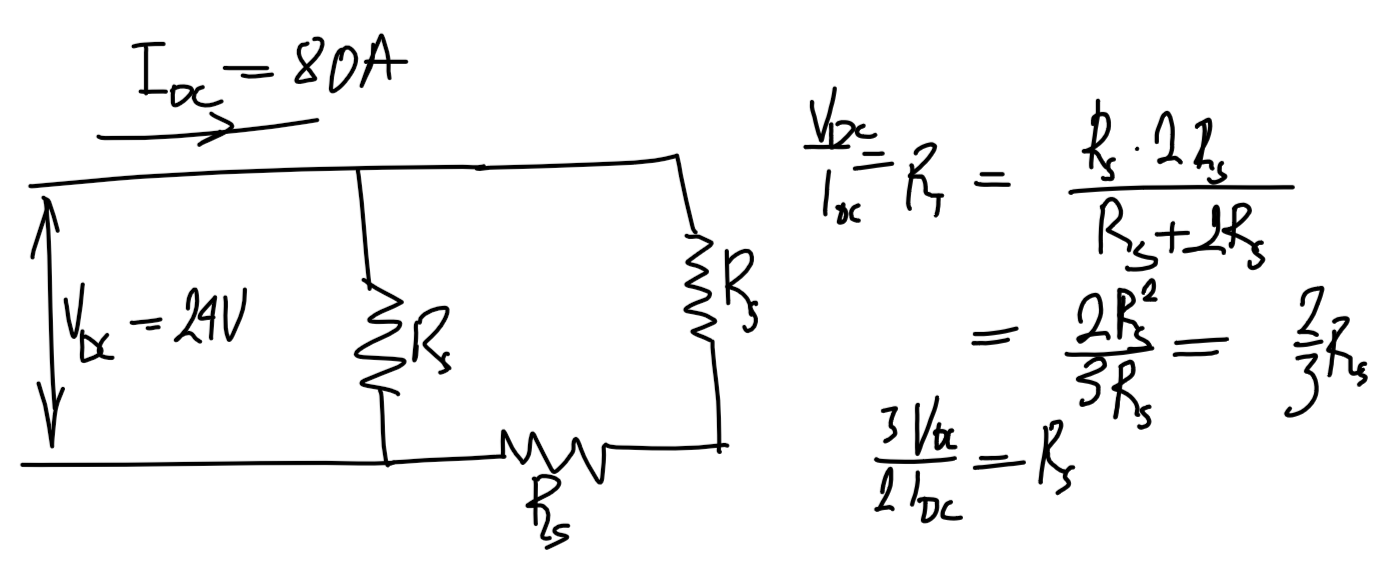
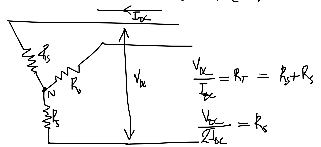
 ### DC test
#### $\Delta$ machine
$$R_s=\frac{3}{2}\cdot\frac{V_{\text{DC},3\phi}}{I_{\text{DC},3\phi}}$$
 #### Y machine
$$R_s=\frac{1}{2}\cdot\frac{V_{\text{DC},3\phi}}{I_{\text{DC},3\phi}}$$
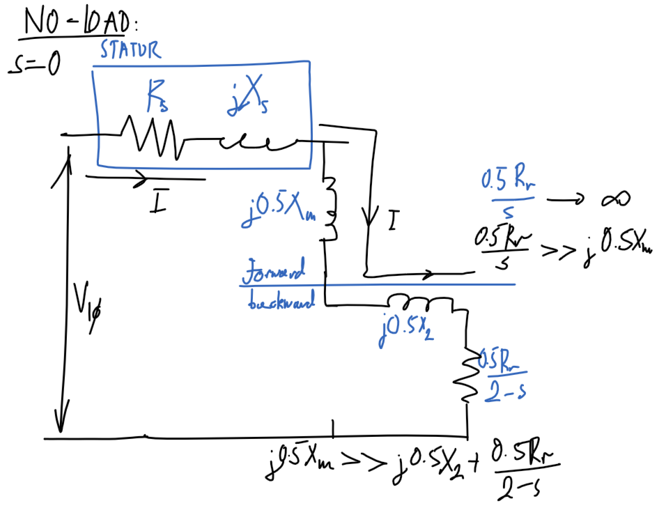
 ### No-load test
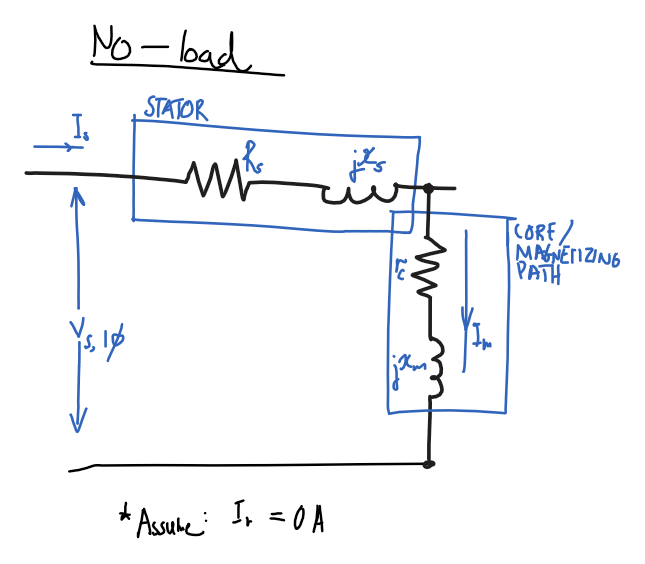
#### Assumptions
- $P_\text{out}=0$
- No output power as no load.
- $R_r/s=\infty$ and $I_r=0$
- Infinite rotor resistance, ignore rotor path.
#### Diagram
Using assumptions, remove rotor part of circuit and only consider stator and magnetizing path.
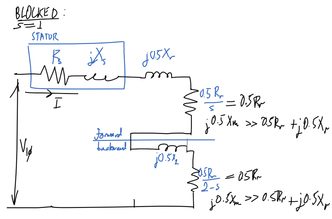
 ### Blocked rotor test
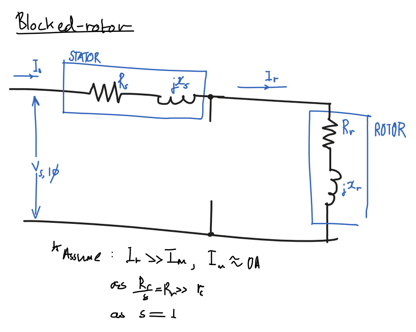
#### Assumptions
- Ignore magnetizing path, $I_m=0$
- $I_r\ggg I_m$ as $R_r/s\ggg Z_m$
- $R_r/s=R_r$, $s=1$
- Slip is $1$ as rotor is blocked.
- $x_s=x_r'$
- Same number of turns in stator and rotor
- and $x_r=f_0/f_\text{BL} \times x_r'$
- Note: $x_r'$ is the inductance at $f_\text{BL}$, the blocked rotor test frequency which is less than the nominal frequency $f_0$
#### Diagram
Ignore magnetizing path
 ---
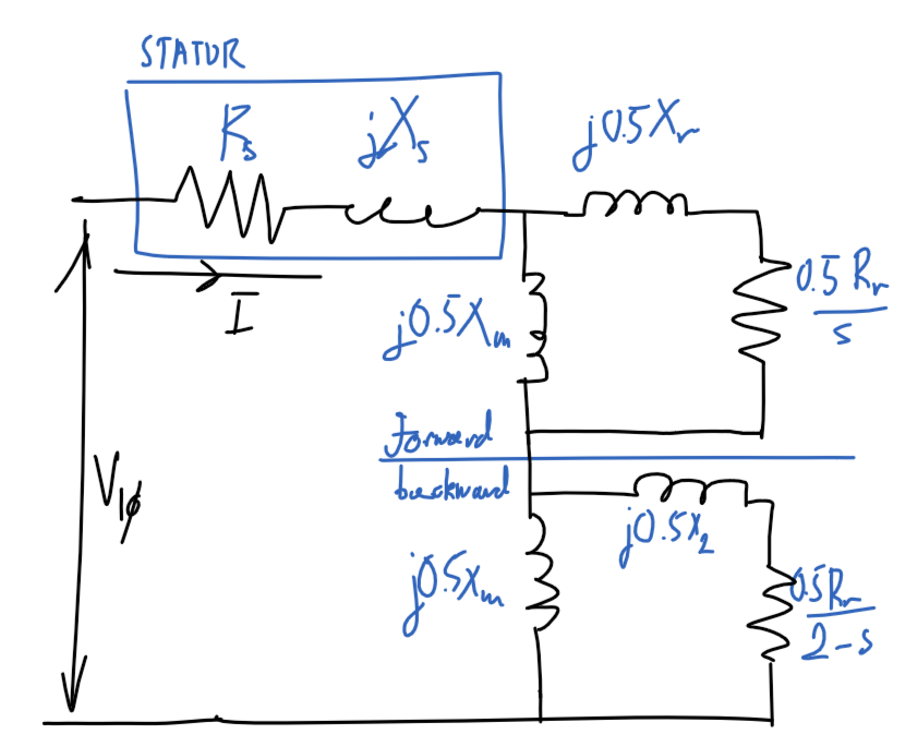
## Single-phase induction motor
### Diagram
 ### Blocked-rotor
#### Diagram
 ### No-load
#### Diagram
 ## Synchronous machine
### Etc
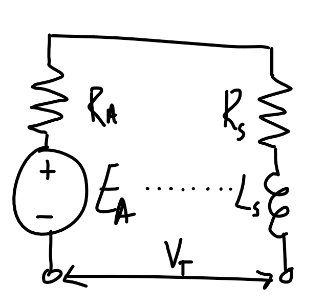
$$E_A=V_{1\phi}-I_A(R_A+j X_s)$$
$$I_A=\text{CONJUGATE}\left(\frac{|S_{3\phi}|\angle\arccos(x)}{3V_{1\phi}}\right), \begin{cases}x=+\text{PF} && \text{lagging} \\ x=-\text{PF} && \text{leading}\end{cases}$$
### Voltage regulation
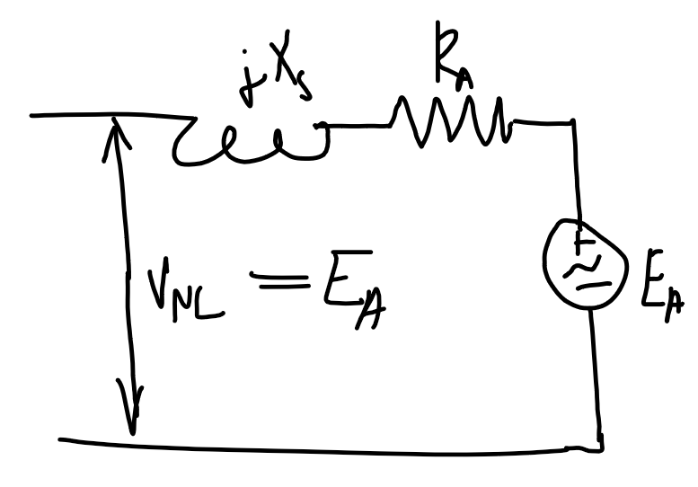
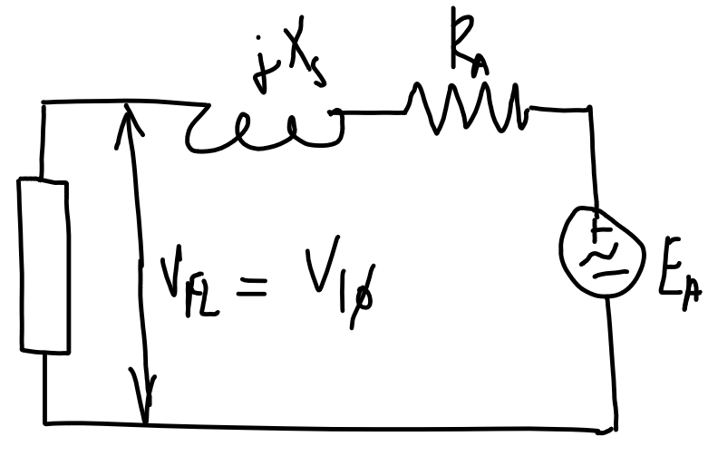
$$\text{VR}=\frac{|V_\text{NL}|-|V_\text{FL}|}{|V_\text{FL}|}=\frac{|E_A|-|V_{1\phi,\text{rated}}|}{|V_{1\phi,\text{rated}}|}$$
- $V_\text{FL}$ is the full-load voltage which is the full-load/maximum rated voltage at the output terminal.
- Calculate $E_A$ at full load by calculating the current as shown above.
- $V_\text{NL}$ is the no-load voltage, which in the no-load case will be $E_A$.
| No-load | Full-load |
| ---------------------------------------------------------------- | ---------------------------------------------------------------- |
|
  |
|  |
| Power factor | Voltage regulation |
| ------------ | ------------------ |
| Lagging | Positive |
| Unity | Near 0 |
| Leading | Negative |
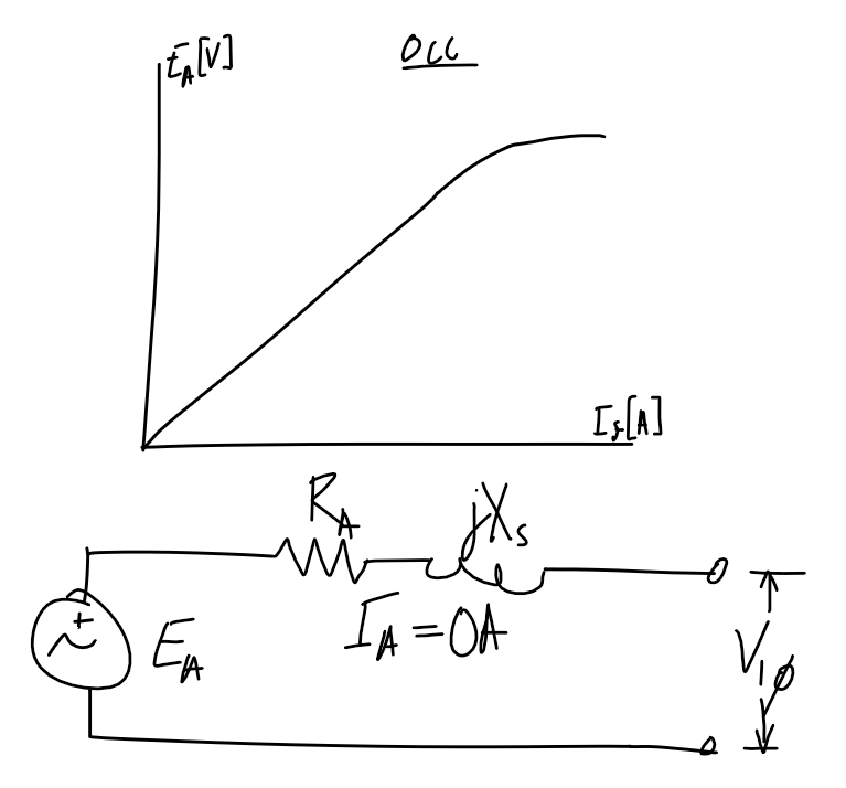
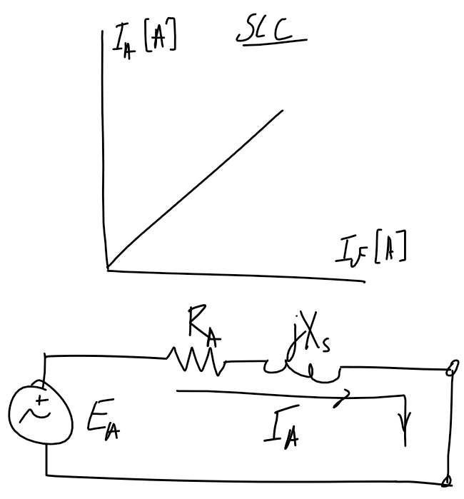
### Open and short circuit test
#### **Note** - double-check if the axis refers to per-phase or line voltage/current.
| Open-circuit test | Short-circuit test |
| ----------------------------------------------------------------- | ---------------------------------------------------------------- |
|
|
| Power factor | Voltage regulation |
| ------------ | ------------------ |
| Lagging | Positive |
| Unity | Near 0 |
| Leading | Negative |
### Open and short circuit test
#### **Note** - double-check if the axis refers to per-phase or line voltage/current.
| Open-circuit test | Short-circuit test |
| ----------------------------------------------------------------- | ---------------------------------------------------------------- |
|  |
|  |
### Power flow
$P_\text{out}$ is the rated power
$$P_\text{out}=S_\text{rated}\times \text{PF}$$
$$
\begin{align}
P_\text{in}&=P_\text{copper}+P_\text{core}+P_\text{F\\\&W}+P_\text{misc}+P_\text{out}\\
P_\text{mech}&=P_\text{F\\\&W}+P_\text{misc}+P_\text{out}
\end{align}
$$
---
### Magnetic circuit analogy
| Magnetic circuit | name | | Electrical circuit | name |
| ----------------------------------- | ---------------------------- | --- | ------------------------ | ----------------------- |
| $$\mathcal F$$ | Magnetomotive force [A-turn] | | $$\mathcal E$$ | Electromotive force [V] |
| $$\mathcal R$$ | Reluctance [1/H] | | $$R$$ | Resistance [$\Omega$] |
| $$\Phi$$ | Magnetic flux [Wb] | | $$I$$ | Current [A] |
| $$\mathcal P=\frac{1}{\mathcal R}$$ | Permeance [H] | | $$G=\frac{1}{R}$$ | Conductivity [$\mho$] |
| $$\mathcal F=\Phi\mathcal R$$ | Hopkinson's law | | $$V=IR$$ | Ohm's law |
| $$\mathcal R=\frac{l}{\mu A}$$ | | | $$R=\frac{l}{\sigma A}$$ |
---
### Transformers
$$Z_P=Z_S\left(\frac{N_P}{N_S}\right)^2=Z_S n^2$$
#### Maximum power.
If load is resistive ($jX_\text{load}=0$) then for maximum power transfer:
$$R_\text{load}=|{R_\text{src}}^2+j{X_\text{src}}^2|$$
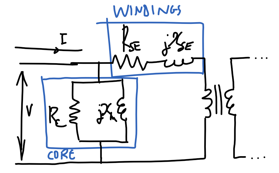
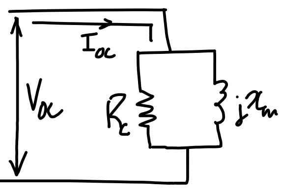
#### Parameter identification
|
### Power flow
$P_\text{out}$ is the rated power
$$P_\text{out}=S_\text{rated}\times \text{PF}$$
$$
\begin{align}
P_\text{in}&=P_\text{copper}+P_\text{core}+P_\text{F\\\&W}+P_\text{misc}+P_\text{out}\\
P_\text{mech}&=P_\text{F\\\&W}+P_\text{misc}+P_\text{out}
\end{align}
$$
---
### Magnetic circuit analogy
| Magnetic circuit | name | | Electrical circuit | name |
| ----------------------------------- | ---------------------------- | --- | ------------------------ | ----------------------- |
| $$\mathcal F$$ | Magnetomotive force [A-turn] | | $$\mathcal E$$ | Electromotive force [V] |
| $$\mathcal R$$ | Reluctance [1/H] | | $$R$$ | Resistance [$\Omega$] |
| $$\Phi$$ | Magnetic flux [Wb] | | $$I$$ | Current [A] |
| $$\mathcal P=\frac{1}{\mathcal R}$$ | Permeance [H] | | $$G=\frac{1}{R}$$ | Conductivity [$\mho$] |
| $$\mathcal F=\Phi\mathcal R$$ | Hopkinson's law | | $$V=IR$$ | Ohm's law |
| $$\mathcal R=\frac{l}{\mu A}$$ | | | $$R=\frac{l}{\sigma A}$$ |
---
### Transformers
$$Z_P=Z_S\left(\frac{N_P}{N_S}\right)^2=Z_S n^2$$
#### Maximum power.
If load is resistive ($jX_\text{load}=0$) then for maximum power transfer:
$$R_\text{load}=|{R_\text{src}}^2+j{X_\text{src}}^2|$$
#### Parameter identification
 | Open-circuit test | Short-circuit test |
| ---------------------------------------------------------------- | ---------------------------------------------------------------- |
|
  |
| 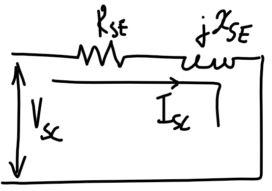 |
#### Voltage regulation
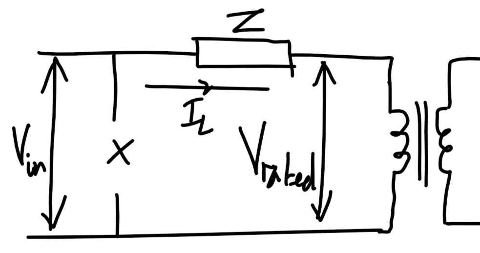
$$\text{VR}=\frac{|V_\text{NL,P}|-|V_\text{rated,P}|}{|V_\text{rated,P}|}=\frac{|V_\text{in}|-|V_\text{rated,P}|}{|V_\text{rated,P}|}$$
Ignore shunt resistance. Refer from primary side. Use KVL to determine $V_\text{in}$.
Voltage regulation is typically small.
$$|V_\text{in}|=|V_\text{rated,P}+I_\text{L,P}\cdot\bar Z|$$
 ### DC machine
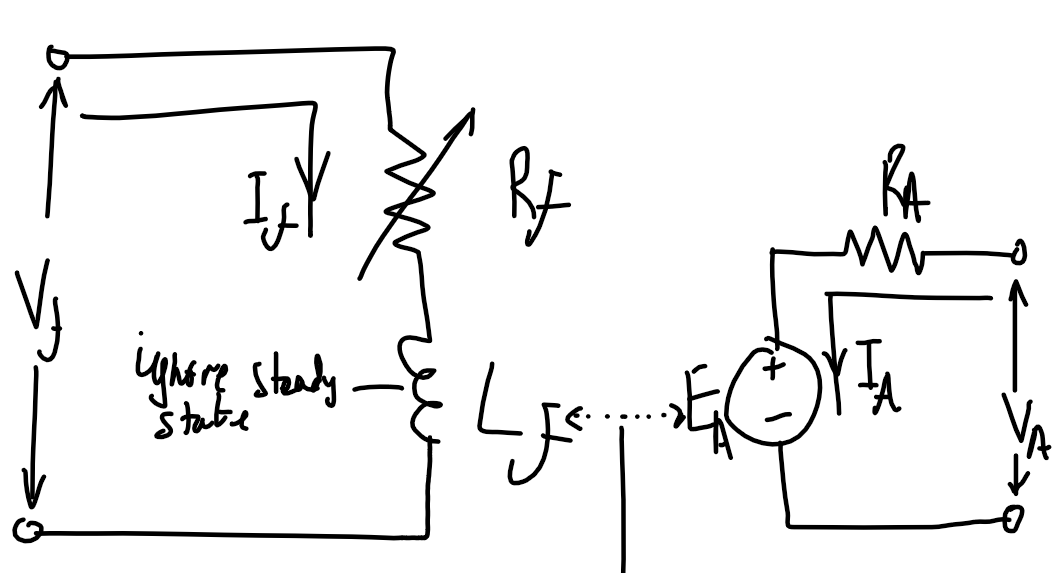
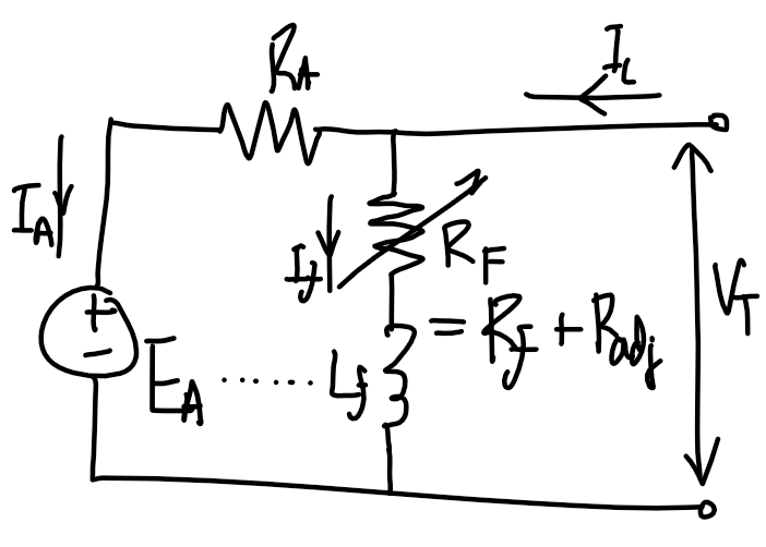
| Separately excited machine | Shunt excited | Series excited |
| ---------------------------------------------------- | ----------------------------------------------------------------- | --------------------------------------------------------------------------------- |
|
  |
|  |
|  |
| | Similar torque-speed characteristic to separately-excited machine | High torque per ampere. Used in high-torque applications |
| Requires two independent voltage sources | | Do not run unloaded - infinite speed at 0 torque as $\omega\propto 1/\sqrt{\tau}$ |
| Motor control using $R_f$ | Motor control using $R_F$ | Motor control using $V_T$. |
#### Starting DC motors
$R_A$ might need to be adjusted so it is high initially in large DC motors, as the starting current is high since there is no back-emf created by $E_A$.
#### Magnetizating curve
When a question specifies the field current or $R_\text{adj}$, refer to magnetization curve. Magnetizating curve is valid at a specific speed $n_{m1}$, and the curve is used to find $E_{A1}$. Using the load condition to find the armature current $I_A=\tau_\text{ind}/(K\varPhi)$, $V_A$ can be used to find a second induced EMF $E_{A2}$. Using $E_{A2}$ find the speed $n_{m2}$ by scaling $n_{m1}$ by $E_{A2}/E_{A1}$.
#### Idk
$$P_\text{mech}=E_AI_A$$
No-load separately excited machine. Assuming no mechanical losses.
$$E_A=V_A\text{ (No load)}$$
$$I_A=0\text{ (No load)}$$
Armature reaction causes increase in speed and causes instability as the core saturates near the poles. Can be reduced with compensating winding which is in series with the armature coil.
$$K\Phi\omega=E_A$$
$$K\Phi I_A=\tau$$
For shunt motor
$$K\Phi=\frac{V_T-R_AI_A}{\omega}$$
$$\tau=K\Phi I_A=\frac{V_T-R_AI_A}{\omega}I_A$$
Assume no saturation, speed locked(?):
This doesn't seem right. We are meant to use the machine constant and the proportionality of current to magnetic flux.
$$\frac{E_{A2}}{E_{A1}}=\frac{I_{f2}}{I_{f1}}$$
|
| | Similar torque-speed characteristic to separately-excited machine | High torque per ampere. Used in high-torque applications |
| Requires two independent voltage sources | | Do not run unloaded - infinite speed at 0 torque as $\omega\propto 1/\sqrt{\tau}$ |
| Motor control using $R_f$ | Motor control using $R_F$ | Motor control using $V_T$. |
#### Starting DC motors
$R_A$ might need to be adjusted so it is high initially in large DC motors, as the starting current is high since there is no back-emf created by $E_A$.
#### Magnetizating curve
When a question specifies the field current or $R_\text{adj}$, refer to magnetization curve. Magnetizating curve is valid at a specific speed $n_{m1}$, and the curve is used to find $E_{A1}$. Using the load condition to find the armature current $I_A=\tau_\text{ind}/(K\varPhi)$, $V_A$ can be used to find a second induced EMF $E_{A2}$. Using $E_{A2}$ find the speed $n_{m2}$ by scaling $n_{m1}$ by $E_{A2}/E_{A1}$.
#### Idk
$$P_\text{mech}=E_AI_A$$
No-load separately excited machine. Assuming no mechanical losses.
$$E_A=V_A\text{ (No load)}$$
$$I_A=0\text{ (No load)}$$
Armature reaction causes increase in speed and causes instability as the core saturates near the poles. Can be reduced with compensating winding which is in series with the armature coil.
$$K\Phi\omega=E_A$$
$$K\Phi I_A=\tau$$
For shunt motor
$$K\Phi=\frac{V_T-R_AI_A}{\omega}$$
$$\tau=K\Phi I_A=\frac{V_T-R_AI_A}{\omega}I_A$$
Assume no saturation, speed locked(?):
This doesn't seem right. We are meant to use the machine constant and the proportionality of current to magnetic flux.
$$\frac{E_{A2}}{E_{A1}}=\frac{I_{f2}}{I_{f1}}$$


