mirror of
https://github.com/peter-tanner/Power-and-Machines-notes.git
synced 2024-11-30 09:00:25 +08:00
8.2 KiB
8.2 KiB
Why are the drawings bad?
I draw them with a mouse
Etc
FIRST-PASS CHECKS
- Double check all are in the correct phase! Multiplications and divisions by
\sqrt{3}or3where necessary must be checked! Try annotating everything that does not have an associated phase. - Check conjugate in current.
\bar{S}=\bar{V}\bar{I}^*
Y-\Delta transformation (Balanced case)
Z_\Delta=3Z_Y
Types of power factors (From ENSC2003)
Where \bar{S}=|\bar{S}|\angle\varphi:
\varphi = \arctan\left(\frac{Q}{P}\right) = \theta_v-\theta_i| Lagging | Leading | Unity | |
|---|---|---|---|
| Voltage | Current behind | Current ahead | In phase |
| Load type | Inductive | Capacitive | Resistive |
Q |
Q>0 |
Q<0 |
Q=0 |
\varphi |
\varphi>0° |
\varphi<0° |
\varphi=0° |
| PF [Load] | [0,1) |
[0,1) |
1 |
| PF [Source] | [0,-1) |
[0,-1) |
-1 |
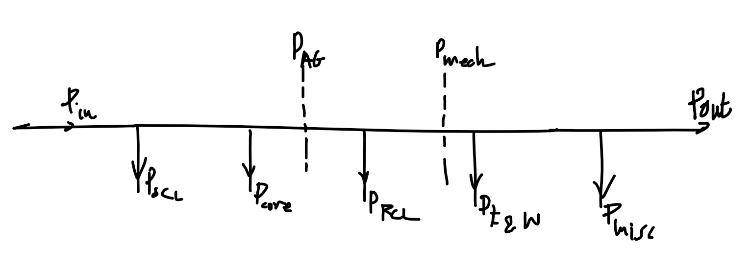
Power types in induction motor
| Type | Description | Equivalent terms |
|---|---|---|
| Input power | Power into machine. V_T=V_{3\phi}, I_L=I_{3\phi} |
P_\text{in}, \sqrt{3}V_TI_L\cos(\theta) |
| Output power | Mechanical output power of the machine, excludes losses | P_\text{out}, P_\text{load} |
| Converted power | Total electrical power converted to mechanical power, includes useful power and mechanical losses inside machine | P_\text{conv}, P_\text{converted}, P_\text{mech}, P_\text{developed}, \tau_\text{mech}\times\omega_m |
| Airgap power | Power transmitted over airgap. | P_\text{AG}, \tau_\text{mech}\times\omega_s |
| Mechanical loss | Power lost to friction and windage | P_\text{mechanical loss}, P_\text{F\\\&W}, P_\text{friction and windage} |
| Core loss | Power lost in machine magnetic material due to hysteresis loss and eddy currents | P_\text{core} |
| Rotor copper loss | Due to resistance of rotor windings | P_r, P_\text{RCL} |
| Stator copper loss | Due to resistance of stator windings | P_s, P_\text{SCL} |
| Miscellaneous loss | Add 1% to losses to account for other unmeasured losses | P_\text{misc}, P_\text{stray} |
\begin{align}
P_\text{in}&=P_\text{SCL}+P_\text{RCL}+P_\text{core}+P_\text{F\\\&W}+P_\text{misc}+P_\text{out}\\
P_\text{AG}&=P_\text{RCL}+P_\text{F\\\&W}+P_\text{misc}+P_\text{out}\\
P_\text{mech}&=P_\text{F\\\&W}+P_\text{misc}+P_\text{out}
\end{align}
Note - assume loss is 0 if not mentioned!
| Type | Description | Symbols |
|---|---|---|
| Load torque, Shaft torque | Torque experienced by load after all losses | \tau_\text{load}, \tau_\text{shaft} |
3\phi induction motor
Etc.
-
Slip speed
N_\text{slip}=N_{s\text{ (sync)}}-N_r=sN_{s\text{ (sync)}} -
"1/4 of rated load" != "1/4 times full load"
- Means 1/4 of full load slip as it is in the linear region. Accounts for the minimum load.
-
Rated power stated in machine specification refers to the output power
P_\text{out}, and excludes all losses. -
Speed regulation using machine speed: $$\text{SR}=\frac{N_{r,\text{NL}}-N_{r,\text{FL}}}{N_{r,\text{FL}}}
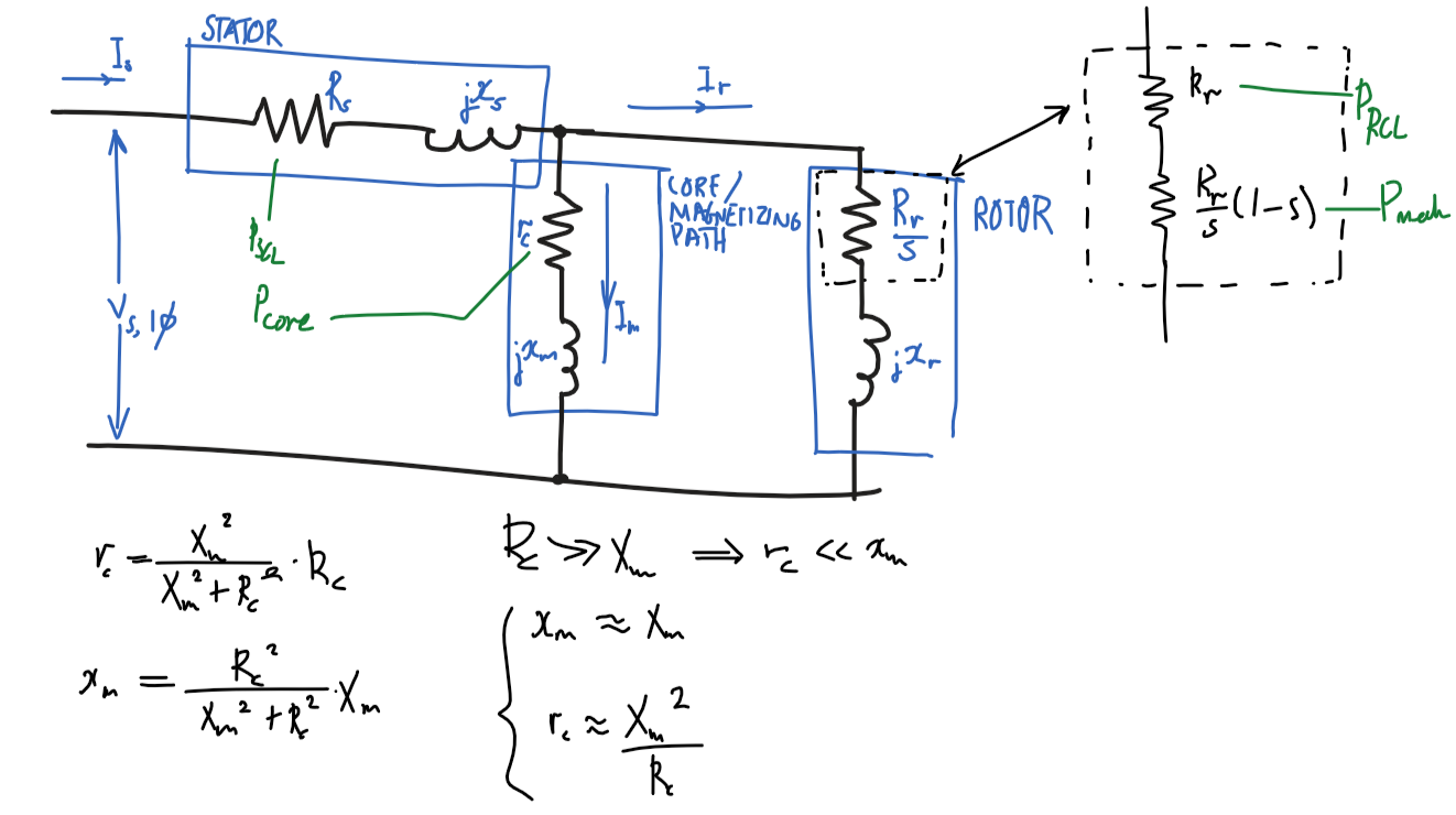
Diagram
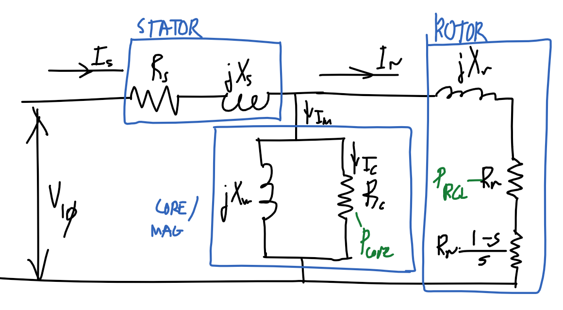
Equivalent model
Assumptions
x_m\approx X_mR_c\ggg X_m\Rightarrow r_c\lll x_mx_m=\frac{{R_c}^2}{{R_c}^2+{X_m}^2}X_m\approx\frac{\cancel{{R_c}^2}}{\cancel{{R_c}^2}}X_m=X_m
r_c\approx {X_m}^2/R_cR_c\ggg X_m\Rightarrow r_c\lll x_mr_c=\frac{{X_m}^2}{{R_c}^2+{X_m}^2}R_c\approx\frac{{X_m}^2}{{R_c}^2}R_c=\frac{{X_m}^2}{R_c}
Diagram
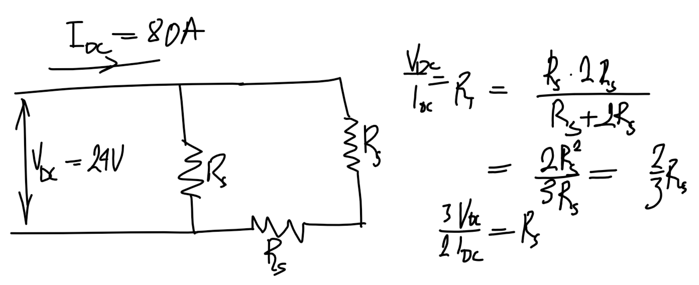
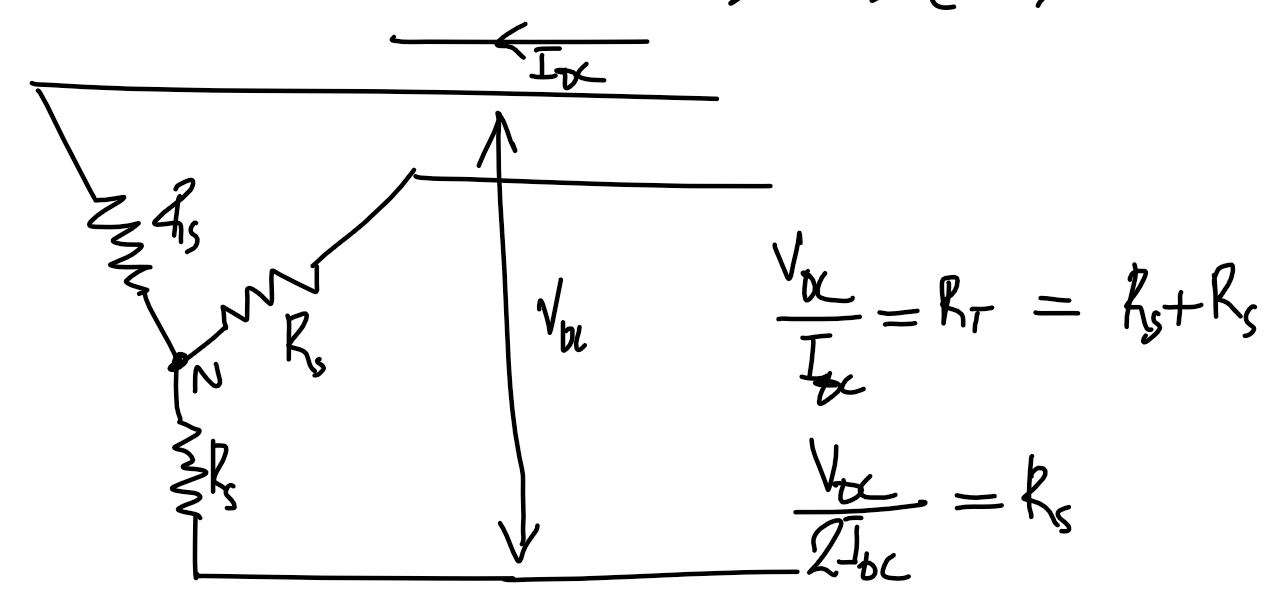
DC test
\Delta machine
R_s=\frac{3}{2}\cdot\frac{V_{\text{DC},3\phi}}{I_{\text{DC},3\phi}}Y machine
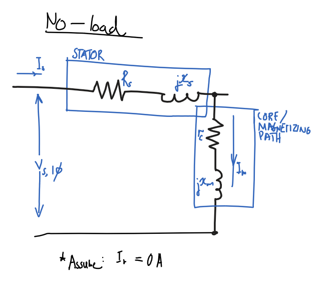
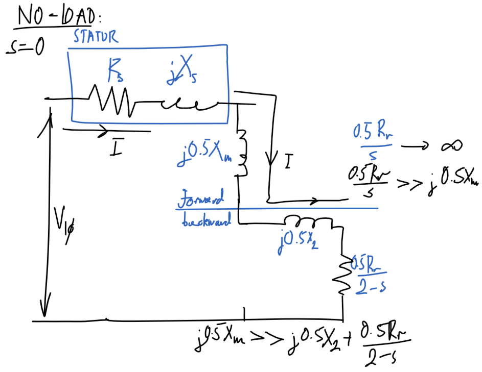
R_s=\frac{1}{2}\cdot\frac{V_{\text{DC},3\phi}}{I_{\text{DC},3\phi}}No-load test
Assumptions
P_\text{out}=0- No output power as no load.
R_r/s=\inftyandI_r=0- Infinite rotor resistance, ignore rotor path.
Diagram
Using assumptions, remove rotor part of circuit and only consider stator and magnetizing path.
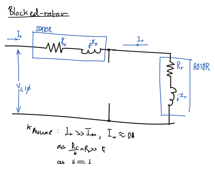
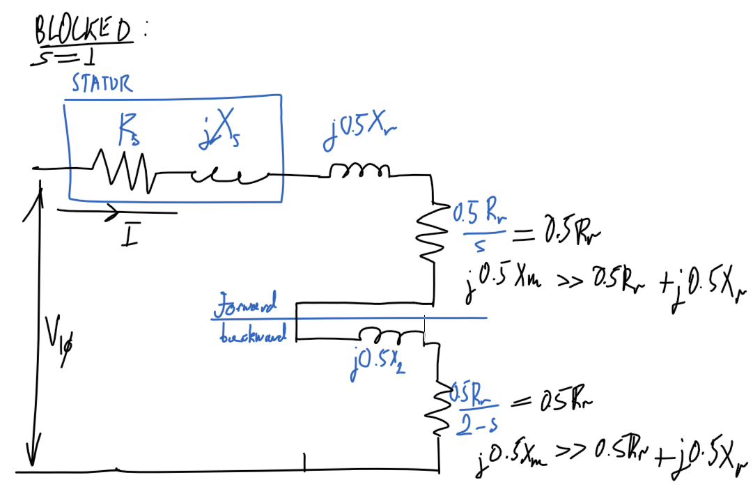
Blocked rotor test
Assumptions
- Ignore magnetizing path,
I_m=0I_r\ggg I_masR_r/s\ggg Z_m
R_r/s=R_r,s=1- Slip is
1as rotor is blocked.
- Slip is
x_s=x_r'- Same number of turns in stator and rotor
- and
x_r=f_0/f_\text{BL} \times x_r'- Note:
x_r'is the inductance atf_\text{BL}, the blocked rotor test frequency which is less than the nominal frequencyf_0
- Note:
Diagram
Ignore magnetizing path
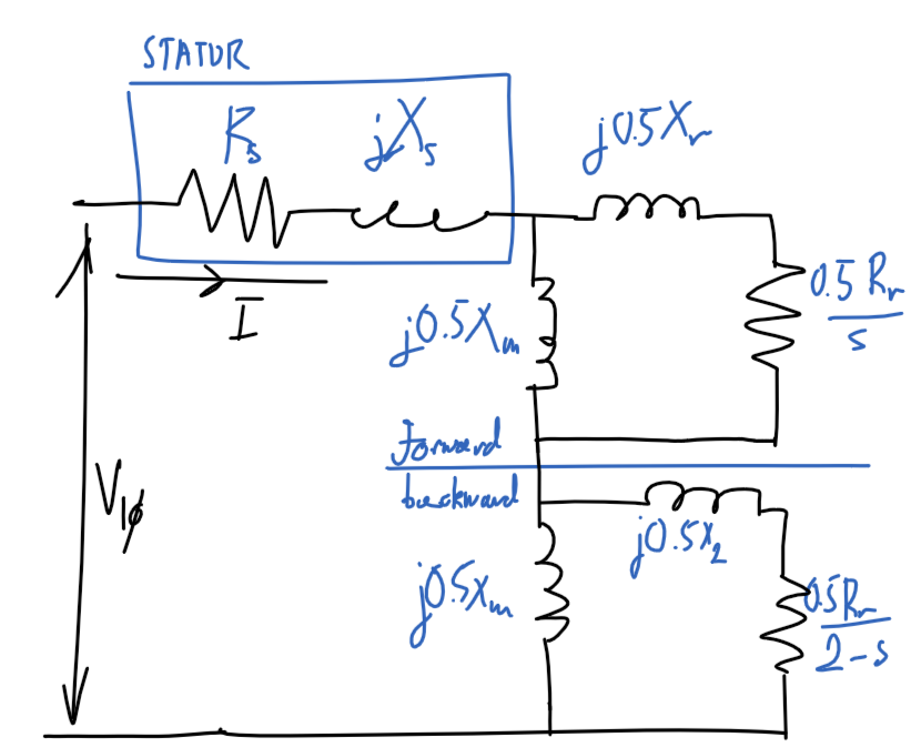
Single-phase induction motor
Diagram
Blocked-rotor
Diagram
No-load
Diagram
Synchronous machine
Etc
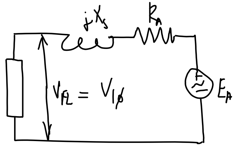
E_A=V_{1\phi}-I_A(R_A+j X_s)I_A=\text{CONJUGATE}\left(\frac{|S_{3\phi}|\angle\arccos(x)}{3V_{1\phi}}\right), \begin{cases}x=+\text{PF} && \text{lagging} \\ x=-\text{PF} && \text{leading}\end{cases}Voltage regulation
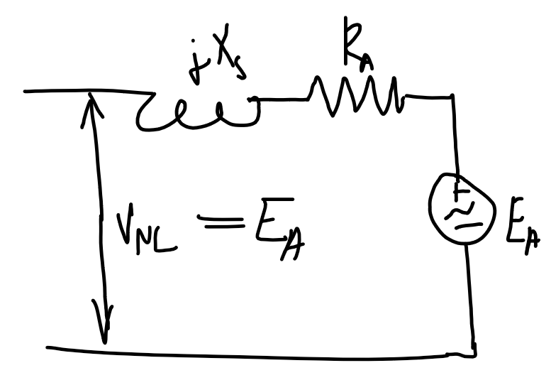
\text{VR}=\frac{|V_\text{NL}|-|V_\text{FL}|}{|V_\text{FL}|}=\frac{|E_A|-|V_{1\phi,\text{rated}}|}{|V_{1\phi,\text{rated}}|}V_\text{FL}is the full-load voltage which is the full-load/maximum rated voltage at the output terminal.- Calculate
E_Aat full load by calculating the current as shown above. V_\text{NL}is the no-load voltage, which in the no-load case will beE_A.
| No-load | Full-load |
|---|---|
 |
 |
| Power factor | Voltage regulation |
|---|---|
| Lagging | Positive |
| Unity | Near 0 |
| Leading | Negative |
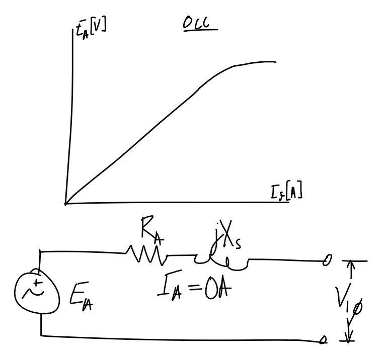
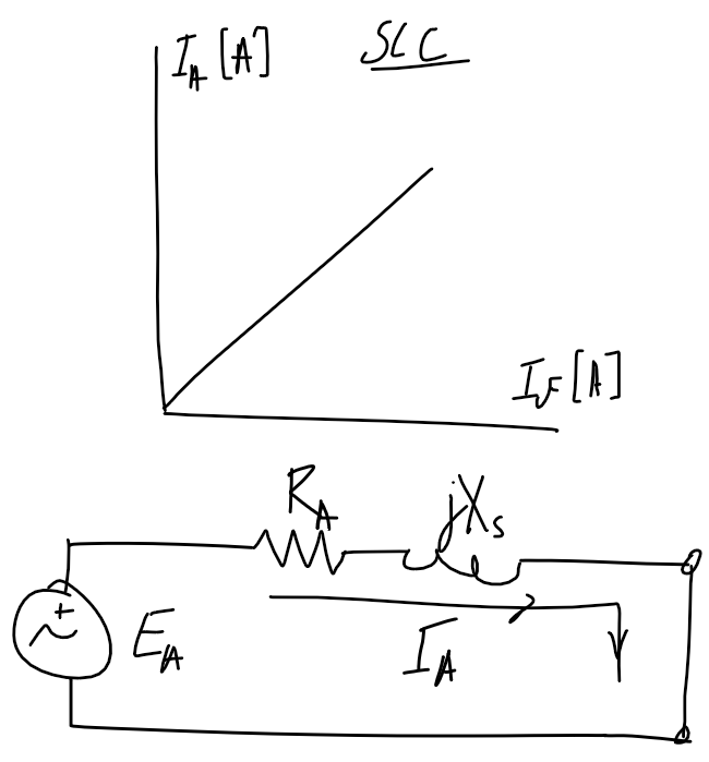
Open and short circuit test
Note - double-check if the axis refers to per-phase or line voltage/current.
| Open-circuit test | Short-circuit test |
|---|---|
 |
 |
Power flow
P_\text{out} is the rated power
P_\text{out}=S_\text{rated}\times \text{PF}
\begin{align}
P_\text{in}&=P_\text{copper}+P_\text{core}+P_\text{F\\\&W}+P_\text{misc}+P_\text{out}\\
P_\text{mech}&=P_\text{F\\\&W}+P_\text{misc}+P_\text{out}
\end{align}
